Greetings,
I am attempting to cleanup very busy electrical
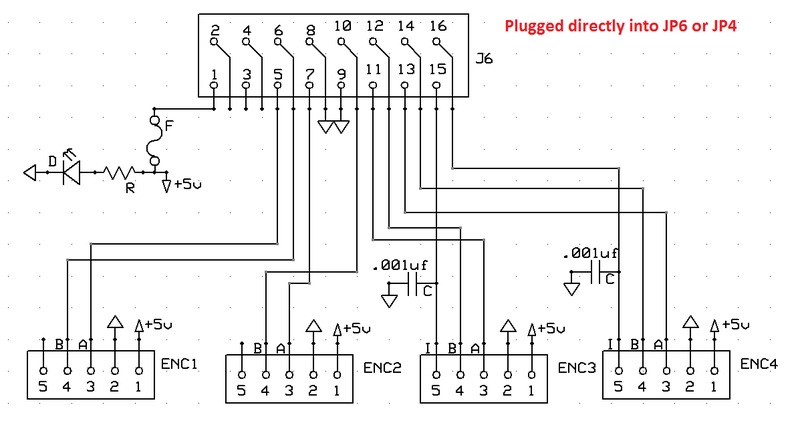
control panels. I am running the KStep closed loop. My
idea is to run all of my encoders directly into the
Kflop board through either JP4 or JP6 using a PC board
with 4 encoder plugs on it. That way I simply plug in my
encoders rather than routing the rats nest of wires
everywhere.
This is my first attempted PC board design. I am
hoping for some suggestions, and have some questions:
- Would it be worth while to add series resistors on the
A, B, and I channels? I seem to be running my encoders
without a problem. Would it be safer to add some 150 ohm
resistors?
- I am adding the 0.001 uf capacitor on the index
channels to help filter noise. Would this be beneficial
on all of the channels?
- All my current encoders are going into the Kflop JP5
ethernet jack - Do you think JP6 pr JP4 will cause
issues?
- Any suggestions??
Thanks!
Scott